CANBuddy
April 2023
This project was inspired by similar products I’ve seen that lets you hook into your car’s OBD II port and read information from that. The ones I’ve seen, however, are incredibly expensive for the hardware that’s used, $300+ for about $20 of hardware.
Being a DIY guy myself, I decided I couldn’t abide that. I needed to just make my own. Don’t get me wrong, I understand charging for your work and time for figuring it out, but if I can do it myself for a lot less and the ability to make it EXACTLY the way I want, I’d rather do that.
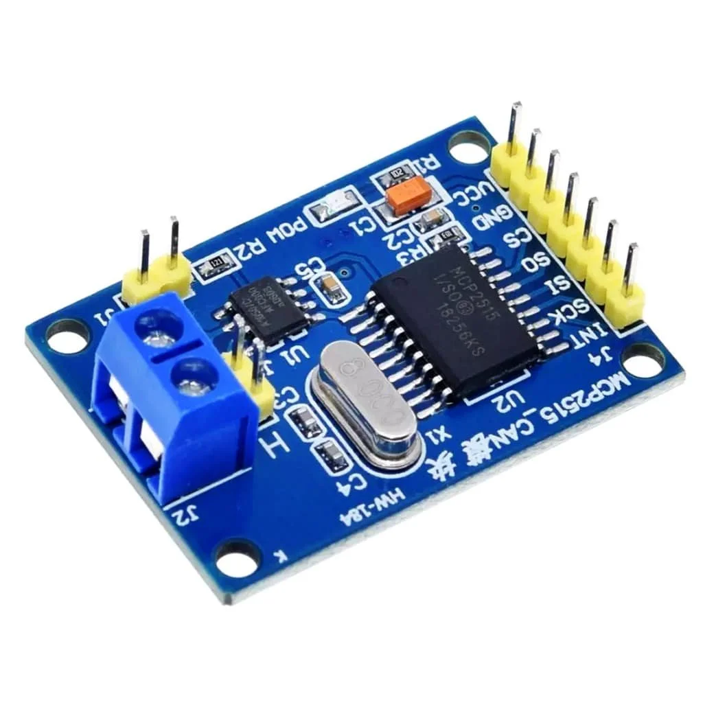
I first looked for a device that would allow the Arduino to interface with the CANBUS. That, naturally, led me to the MCP2515 and its respective breakout board from amazon. For my first test, I purchased a wired, male OBD plug. I then isolated the battery voltage, signal ground, CAN HI and CAN LOW. In the final design I will use power from the OBD port most likely, but for now I am only using the ground wire to make sure the signals and the Arduino have a common ground, and I’m using the power from my computers USB port.

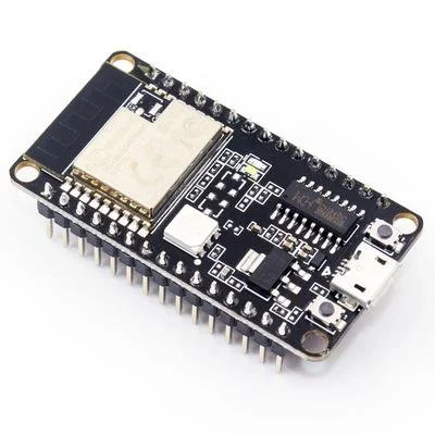
I was using an Adafruit Feather 32u4 datalogger at the time of the first test and will most likely use either that board, the M0 version of that board, or a different setup all together using a raspberry pi, or ESP32 for its on-chip CAN abilities. For now, I’m using the 32u4 datalogger still for its ability to dump data onto the SD card for later analysis.
I have not selected a screen yet, but I would like to use the larger 2.5-ish in, 128x64 SSD1309 display instead of the smaller .96in SSD1306 display to improve visibility while driving. This, however, is not set in stone and could change in the future.
I used cmp_can to try to get CANBUS data to appear on the arduino’s serial monitor. So far I have been able to pull hex data from the OBD II, but have yet to interpret, or read through the code to understand how this system works more clearly. I also plan to trim down the code to only return the codes requested (filtering) and add the ability to change what data is displayed on the screen.

One strength of the ESP32 is it’s on-board CAN ability, which allows it to interface directly with the OBD II port without the need for the MCP2515. The code that I have seen so far for this setup is MUCH simpler than the similar applications that use the MCP2515. I have yet to test the libraries for this chip though, and I am hesitant to lose the ability to write to an SD card.
I could use another breakout board for an SD card interface, but would rather not for simplicity. It may become apparent that most people don’t care about writing to an SD, and the ESP32 would work fine. Even if I select an ESP32 for the chip I use in the final design, I will likely keep using a variant of the Adafruit Feather Datalogger for the duration of the development for is on-board SD card capabilities.
May 2023
I ordered the ESP32 and Raspberry Pi Shields. Until they arrive, I am trying to get another method to work, using an ELM OBD2 to USB adapter with a raspberry pi, using the python-OBD library. From the examples I’ve seen, using the ECM327 appears to be a simpler method to receive human readable data off of the OBD2 port.

I’m hoping this shotgun approach to figuring out what will work best will yield the earliest arrival to a functional prototype. Given the relatively low cost of the components, fortunately this isn’t a cost prohibitive approach for this project.
One advantage of using a raspberry pi is the ability to log in and modify the code headlessly. Since the ECM327 to USB adapter uses the USB on the raspberry pi, very little wiring is needed as well. All-in-all, this is the simplest approach yet. With the HDMI-out of the raspberry pi, it also allows a much greater degree of flexibility for screens. On top of all that, since the raspberry pi has an SD card integrated onto it as well, datalogging is made very simple to store and to retrieve.
Another bonus of using a raspberry pi to operate the CANBuddy is the on-board Wi-Fi. This would conceivably allow a simple data transfer to take place at the end of each drive, storing all data files to a cloud or network storage every time the engine is turned off within the range of your home Wi-Fi. If the engine is turned off outside of the range of your home Wi-Fi, it will store it on-board until it is within range again, and dump all the temporarily saved files to your cloud service of choice when it arrives back home.
July 2023
Unfortunately this project is currently on hold until I can either find a CAN db file for the IDs on the new GR86/BRZ (ZD8/ZN8) ECU or if I can pull the necessary readings from the OBDII port.
I am also trying to focus my efforts on the Debugger Buddy project since I’m in a position to accomplish much more on that project at this time. Ultimately, with limited free time, I try to devote time to the project I can make the most progress on at the time.